This is the third fish on the new rod. The first two were smaller and Dale wasn’t close by with his camera. This Brown from the Poudre River about fifteen miles from Fort Collins, Colorado measured thirteen inches. I was fishing a chartreuse Copper John as a dropper under a orange body Humpy, and was surprise that he took the dry this early in the season.
Picking the line weight was a lengthy project. I was able to try a couple of five weights one evening, and then it snowed the next day. A week later I tried a six weight. Both cast well. I paced off a 66 foot cast with a WF #5 line. That’s not bad with a soft action 71/2 foot rod. The six weight loaded the rod more easily, but didn’t add much to the distance.
 In the end I settled on a five weight double taper (Cortland 444 Classic Sylk). Cortland says, ” It is the first modern line designed specifically for fine bamboo rods. The ‘Sylk’ replicates the fine diameter, long taper, supple feel and subtle color of natural silk.” Don’t worry, fiberglass rods like it too. The accuracy and delicate delivery of a fly are determined by the length of the front taper and the caster’s skill. Additionally, the greatest control is had when the belly of the line is in the guides at the casting distance. This is what a double taper is designed for. It’s not the best distance line, but I have other distance rods with weight forward lines.
  This rod is about the experience, the tradition, and the uniqueness. There is not another one in the world. Someone may have a blank stored away, but Rick’s Rods doesn’t. I do have four other light weight blanks, but they are all sanded and would produce a different appearance. This rod is about the experience, the tradition, and the uniqueness. There is not another one in the world. Someone may have a blank stored away, but Rick’s Rods doesn’t. I do have four other light weight blanks, but they are all sanded and would produce a different appearance.
This is a fishing rod, and fishing is where it will often be. I do think I will show it to Wright-McGill in Denver. There may be someone there who remembers the fiberglass days, and maybe I can get a W-M rod case.
[print_link]
[print_link]
After lots of delays and distractions, I finally put the first coat of finish on the wraps yesterday. I should be casting in two more days. At the start I said that this wouldn’t be a blog about beginning rod building, but I will mention some of my techniques. In all of our crafty endeavors we start with a teacher or book and integrate skills and knowledge over time to produce our own style. That’s what I’m talking about here, style or what works for me.
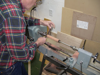
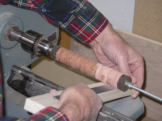 Lets start with the cork grip. I begin with cork rings that you see in post #4. These are placed on 1/4 inch all-thread with a layer of Weldwood Plastic Resin Glue between rings. Nuts are tightened down to compress the rings until glue is squeezed from all joints. This process has always resulted in a grip without viable joints between rings. The assembly is chucked into the lathe and turned to shape. My first step is to sand the grip round with 100 grit cloth on a wood block. This results in the cork being concentric around its axis. At this point I shape the grip using 100 through 600 cloth and paper. The grip is removed from the all-thread by holding the grip in one hand while spinning the shaft in reverse with a drill motor.
 The inner ID of the grip has to be reamed with rat tail files and reamers until it fits over the rod. Once a good fit is achieved, I glue the grip in place with 2 Ton Clear Weld Epoxy. Some folks will ream individual cork rings (less work) and assemble the grip on the rod. They then chuck the rod butt section in a “rod lathe” and shape the grip. I would have to acquire a roller steady rest for my lathe before using this method. The results are the same. The inner ID of the grip has to be reamed with rat tail files and reamers until it fits over the rod. Once a good fit is achieved, I glue the grip in place with 2 Ton Clear Weld Epoxy. Some folks will ream individual cork rings (less work) and assemble the grip on the rod. They then chuck the rod butt section in a “rod lathe” and shape the grip. I would have to acquire a roller steady rest for my lathe before using this method. The results are the same.
I glue the reel seat in place with the same glue. I have learned by experience to first dry fit the seat and mount a reel. This allows me to assure that the reel will align with any guides on the butt section. Carefully placed alignment marks work for this purpose, but there’s nothing like a visual check before getting out the epoxy.
In post #5 I explained guide spacing, and rod spline in #6. With this information the guide locations are marked. Marks can be made with pencil if they show up. This is convenient because the marks are easily removed with alcohol on a Q-tip. Before placing the guides, I wrap the ferrules without the guides in the way. Aligning guides can seem to take as much work as wrapping. I tape guides in place and then look through the guides checking that they appear to align. I then look down on the rod section checking that there is an equal amount of each guide visible on each side of the rod.
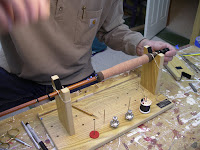  My fishing buddy, Jim, showed me how to wrap a second color (gold metallic) embedded in the primary color (black). If you are interested, reply to this post, and I will try to describe the process. After some practice I was able to wrap a guide pretty quickly. I have one strong recommendation. Take time to prep the guides. By this I mean filing and honing down the leading edge of each guide to a knife edge without any burrs. If you don’t, you will fight the wrapping effort. I found the Hopkins-Holloway guides required very little preparation. My fishing buddy, Jim, showed me how to wrap a second color (gold metallic) embedded in the primary color (black). If you are interested, reply to this post, and I will try to describe the process. After some practice I was able to wrap a guide pretty quickly. I have one strong recommendation. Take time to prep the guides. By this I mean filing and honing down the leading edge of each guide to a knife edge without any burrs. If you don’t, you will fight the wrapping effort. I found the Hopkins-Holloway guides required very little preparation.
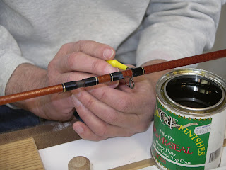 Finally, it’s time to finish the rod. Today graphite rods are finished with a two part epoxy, which is only placed on the wraps. This is often applied very thick. Years ago bamboo was wrapped with silk thread and finished with varnish. As fiberglass rods were built between bamboo and graphite, I used an in between process. Wrapping thread is nylon and the finish is General Finishes Arm-R-Seal. It is a tung oil/urethane finish that was recommended by a bamboo rod builder who also uses it on fiberglass. I will put at least three coats on the wraps, and then another two coats on the fiberglass and wraps. The glass doesn’t require a finish, but I like the look.
In the next post I will tell you what line weight the rod likes and have finished pictures. Surely you can’t wait. At least I’m anxious to get to what this project is all about — fishing.
[print_link]
How can you break your rod while casting? I’ll get to that, but first let’s think about the strength of a rod. Fiberglass is a very strong material that resulted in a rod lighter than bamboo, but not as light as modern graphite. Fiberglass rods were initially designed to cast like soft bamboo, and still can’t produce the fast action of graphite, but it can take more abuse.
I mentioned in the last post that most of the fibers in the material run the length of the rod. This arrangement resists bending and makes a stiffer rod. The stiffer it is, the faster the action is. Weight of the rod (not line weight) is the trade-off. Graphite wins in the fast vs light competition. Fibers also wrap around the rod. These provide radial strength and keep the rod from deforming too far out of round under bending stress. Though a fiberglass rod won’t cast the distance of a graphite, it will produce a more delicate and controlled cast than graphite. The bamboo guys will argue that cane rods are even more delicate and controlled.
Rods get abused when I fish. There is the yearly fall into the rocks, which is the reason I avoid expensive reels. There is also the larger fly hook hitting the rod at many miles per hour during an marginally controlled cast. Both situations can nick the surface fibers of the rod. This creates a weak spot. Graphite has a softer surface, thinner wall thickness, and faster line speed (fly velocity), and suffers greater damage.
A fly rod is designed to have high bending strength and adequate radial strength. It’s not designed to have high resistance to twist. This leads to a weakness you can exploit if you wish to break your rod. Casting sidearm is a useful technique in a variety of situations. Double hauling sidearm is powerful, but puts great stress on the rod. The caster must apply enough power to keep the line from dropping to the ground during the back cast. It’s necessary to keep your thumb behind the direction of the cast so that the guides face in that direction. Look at the diagram and imagine the twist put into the small diameter tip section of the rod if the line is pulling as shown. Always keep the guides and reel aligned with the direction of the cast. radial strength. It’s not designed to have high resistance to twist. This leads to a weakness you can exploit if you wish to break your rod. Casting sidearm is a useful technique in a variety of situations. Double hauling sidearm is powerful, but puts great stress on the rod. The caster must apply enough power to keep the line from dropping to the ground during the back cast. It’s necessary to keep your thumb behind the direction of the cast so that the guides face in that direction. Look at the diagram and imagine the twist put into the small diameter tip section of the rod if the line is pulling as shown. Always keep the guides and reel aligned with the direction of the cast.
Here is another tip breaking technique that works best on fast action rods that bend mostly in the tip section. Before you cast, when first pulling line out through the guides, grab the leader and pull down parallel to the raised rod. This forces the maximum bending stress into the tip section at its smallest diameter. It’s much harder to break the rod if you pull away from it, which applies the stress against the rod length.
Lastly, we can break the rod at the ferrule. Again, this is best done during a sidearm cast. I discovered this while practicing with a 9 weight rod. The middle rod section slipped forward during a double haul cast. This put all the bending stress on two points as seen in the diagram. Point 1 couldn’t break through the side, but the rod split at Point 2. I’ve also had the rod tip section come loose on light rods and fly out into the water. The first reaction is to look around and assure that no one saw that happen, then I retrieve the section and put the rod together again. There is a solution to this problem — St. Croix Ferrule Wax. Apply it to the male ferrule and they won’t slip. on two points as seen in the diagram. Point 1 couldn’t break through the side, but the rod split at Point 2. I’ve also had the rod tip section come loose on light rods and fly out into the water. The first reaction is to look around and assure that no one saw that happen, then I retrieve the section and put the rod together again. There is a solution to this problem — St. Croix Ferrule Wax. Apply it to the male ferrule and they won’t slip.
I’ve gotten off on a bit of a casting tangent. But my rods suffer enough during normal use, so I try not to add to it through improper use. In the next post I will discuss assembly of the rod, and in the last post I’ll find the right line for it.
[print_link]
Build a fiberglass rod, how do they do that?
First a steel mandrel is machined to what will become the inside diameter and taper of the finished rod blank. Each rod weight and action will have a different size mandrel. The uncut blank that I started with would have had a full length mandrel. Contemporary graphite rods often have a built in ferrule. The butt end of one section slips over the tip end of its mate. These have to be manufactured as separate sections.
The material that wraps the mandrel is fiberglass with many more fibers running lengthwise than crosswise to the rod. It is impregnated by the supplier with a resin glue, and is then called pre-preg. The fiber specifications, their orientation and the resin used are all design parameters that determine the rod characteristics. Early rods were made of E-glass and the later rods of S-glass. I have to assume that my rod is S-glass because that is what would have been in inventory when Wright-McGill stopped making fiberglass rods. S-glass is somewhat stronger, and can produce a stiffer and lighter rod.
The pre-preg is wrapped around the mandrel, and that is wrapped with a heat shrinking cellophane. Here again, the wrapping technique impacts the finished rod’s performance. At this point the mandrel is hung in an oven to cure. The cellophane shrinks when heated. This puts pressure on the pre-preg in which the resin has liquefied. The excess resin is squeezed out, and the rod continues to cure — harden.
The mandrel is removed from the cured rod as is the cellophane. At this stage spiral ridges caused by the uneven cellophane pressure remain. These were most often, but not always, sanded off. My blank has the ridges. I don’t know if they would have been sanded. Not all companies sanded the blanks, but I believe W-M did. I’m leaving mine. By the way, W-M started making fiberglass rod in 1952 and continued into the early 70’s. At one point they were making 500 a day. Most would have been spinning and casting rods.
If you are interested is further detail, “The Technology of Fly Rods” by Don Phillips is an excellent resource. It’s out of print, but available through inter-library loan. I think I will leave rod strength for the next post.
 [print_link] [print_link]
Well the chairs are complete along with other household projects, and now I’m back to fly rods. It seemed like I painted forever. Thirty-nine parts per chair got two coats of paint on all sides and then the assembled chair received a third. I can tell you how to clean a brush and modify latex paint so that it will dry slower and streak less, but that’s a different story.
The whole thing about 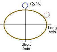 rod spline is about deciding what side of the blank to place the guides on. If you think of the cross section of a rod, fiberglass or graphite, being oval shaped instead of round, you can visualize what happens when it is bent. The rod will want to bend in the direction of the Short Axis. Place the guides on the Long Axis and the rod will be unstable. It will insist on bending to one side or the other toward the Short Axis. The same is true if the guides are located off axis like the dotted red guide. Guides not on or opposite the spline will cause a twisting stress in the rod and a wave in the line as the rod vibrates during the cast. The wave will decrease your accuracy and distance. rod spline is about deciding what side of the blank to place the guides on. If you think of the cross section of a rod, fiberglass or graphite, being oval shaped instead of round, you can visualize what happens when it is bent. The rod will want to bend in the direction of the Short Axis. Place the guides on the Long Axis and the rod will be unstable. It will insist on bending to one side or the other toward the Short Axis. The same is true if the guides are located off axis like the dotted red guide. Guides not on or opposite the spline will cause a twisting stress in the rod and a wave in the line as the rod vibrates during the cast. The wave will decrease your accuracy and distance.
Finding the spline is easy. Place the butt end of a section on a hard surface and support the tip end with one hand while pressing in the center to cause a bend. Now by rolling the rod you will cause it to snap to its comfortable position, as if the flat side of the oval were on the surface. Likely you will find another comfortable position opposite the first. One may feel more significant than the other. Mark the upward side of the rod section. This is the inside of the curve. The Spline is commonly said to be the bottom side or outside of the curve.
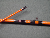
I marked my rod blank before cutting it. After the ferrules were installed I checked each section and the assembled blank. I’m checking the assembled middle and tip section in the picture. In all cases the spline was still where marked.
The guides will be located  in line with the mark and as indicated in the diagram. By the way, I can’t measure with a dial indicator that my blank is more than 1% of its diameter out of round. Spline is easy to visualize as the result of your rod being oval, but it is really the sum of manufacturing characteristics that cause it to bend one direction more easily than any other. There are arguments for placing guides on the spline side and opposite. They involve having the greatest bending resistance when casting forward or pulling backward (fighting a fish). I don’t believe it matters, and it’s easier to mark the rod as I described. The serious error would be to align guides off the Short Axis, and differently on each section. This would maximize vibration and stress. in line with the mark and as indicated in the diagram. By the way, I can’t measure with a dial indicator that my blank is more than 1% of its diameter out of round. Spline is easy to visualize as the result of your rod being oval, but it is really the sum of manufacturing characteristics that cause it to bend one direction more easily than any other. There are arguments for placing guides on the spline side and opposite. They involve having the greatest bending resistance when casting forward or pulling backward (fighting a fish). I don’t believe it matters, and it’s easier to mark the rod as I described. The serious error would be to align guides off the Short Axis, and differently on each section. This would maximize vibration and stress.
In the next post I will briefly discuss rod strength and manufacturing along with a caution about how not to break your rod while casting.
[print_link]
I used to think that guide spacing was a science known to rod manufactures who designed spacing to fit the performance of their individual rod models. It’s not that complicated. The task is to uniformly locate the guides along the rod without placing a guide on a ferrule. Here’s my logic.
- The first guide (1) is typically 3.5 to 4.5 inches from the tip, and the stripping guide tends to be 28 to 30 inches from the butt. A 7.5 foot rod commonly has 8 guides not counting the tip guide. That makes the stripper number 8.
- I could place a guide every 8 inches between with the first at 4 and the stripper at 60. That would look very odd. It would have guides widely spaced toward the tip where the rod bends the most and narrowly spaced toward the butt where there is little bend. Logically the spacing should increase with each guide from the tip to the butt.
- The distance tip to guide 1 is X, and the space between 1 and 2 is X + an increment (I). Then from 2 to 3 is X + 2I, from 3 to 4 is X + 3I, and so on.
- This leads to the formula: Tip to Guide N is Dn=N*X+I*N*(N-1)/2. I won’t attack you with the formula development, but it comes from the algebra of number series.
- Knowing where the first and last guide will be located allows me to calculate I=(Dn-n*X)/(n*(n-1)/2), where n is the number of guides.
I created a spreadsheet to do the calculations. The inputs are Rod Length, # of Guides, Stripping guide to Butt, Tip to Guide 1, and ferrule locations. The graph shows the results. I had to change the Stripper or First guide location several times to avoid locating a guide on a ferrule.
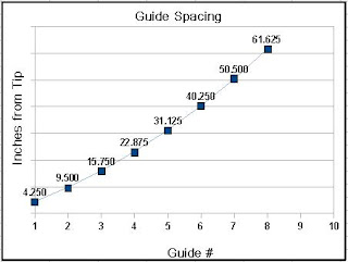
I also considered the spigot ferrule design. The spigot is glued into the larger section, which makes it very strong. The smaller section slips over the spigot. It needs to be wrapped to reinforce the fiberglass, so I need at least an inch between the ferrule and the guide. Ferrules are at 29.625 and 59.625. For convenience, the spreadsheet rounds the results to eights of an inch.
In the next post I will discuss locating the spline of the rod so that I know which side to place the guides on. After that the actual work of rod building starts.
The spreadsheet is available to you, just click here: Guide Spacing
[print_link]
Merry Christmas all. The ground’s been covered with snow for several weeks. This is unusual in this part of Colorado. I deal with my fishing withdrawals by doing a little casting on the grass. Now I’m suffering.
I’ve gotten committed to building four Adirondack chairs and had to take down the rod building to make room for chair painting — 39 parts per chair — two coats, then a final coat on the assembled chair.
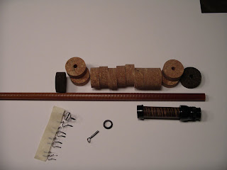
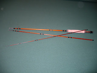
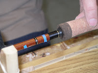
Here is a picture of the component parts for the rod. I chose a Curly Koa wood spacer because the color is similar to the rod blank and the curl highlights the similar curl in the blank. The guides are Hopkins-Holloway titanium, chosen for their finish and in hope that they would require less preparation. The cork is red colored burl and burnt burl. The components all came from Anglers Workshop.
I won’t turn the blog into a beginning rod building class. You will see features of the rod being built, and I will present information that I didn’t find readily available. You can find good reference information at Flex Coat and a good document by Al Campbell that discuss rod building from the start.
The next post will get back to serious stuff when I determine the guide spacing. I’ve developed a spreadsheet that aids in spacing guides so that they don’t fall on a ferrule location.
 [print_link] [print_link]
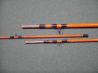
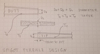
A spigot is a tapered plug for the hole in a cask, thus we have a “spigot” ferrule. The blank is cut. A tapered spigot is fit into the butt section so that it protrudes an inch or so through. The tip section fits over the protruding spigot, and we have our spigot ferrule (below). I will call it a “tip over butt” ferrule because the tip (female) fits over the butt (male), which is opposite a standard metal ferrule configuration to the right.
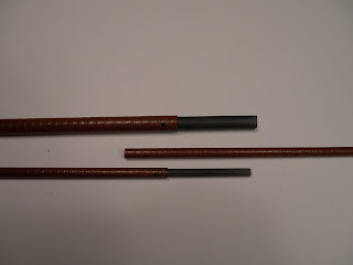
I first cut a few inches of the butt of the blank to get a total length of eight feet, and then cut that into three equal length sections. Actually I marked the rod spline before cutting. More about that later. At each cut I recorded the inside diameter and taper. See the drawing.
The only thing that holds the rod together and aligns the sections is the press fit of the spigot into the blank. The taper being the same as the inside of the blank is the most critical parameter. That is why I choose to have Devo the machinist turn the spigots.
The first challenge was finding material to make the spigot. The diameter is small enough that solid stock is required. I found carbon fiber rod at Aerospace Composite Products, and for $23 purchases enough for half a dozen rods of this size.
Devo turned two spigots so accurately that when fitted together without glue the rod sections could be assembled and whipped around like we all do when picking up a new fly rod. Gluing the spigot into the butt section requires some thought and preparation. I used two-ton water proof epoxy. After mixing I heated it in the microwave for ten seconds. This changed the viscosity so that it was more liquid and could form a thinner layer on the inside of the blank. Glue was applied with a Qtip, and the spigot dropped into the butt section. Preparation meant that I had a dowell ready to push it through the glue. It also meant that after giving it a twist to spread glue, and pulling it tight I had a rag pre-wetted with acitone to wipe the protruding spigot clean.
The next day I slid the tip sections onto the spigots and marked how much to cut off the large ends of the tip sections to have a 1/4 inch gap when reassembled. This gap allows for wear in the future. I will always be able to assemble the sections without the two pieces of rod butting together before the fit is tight. By the way, I cut the blank with a carbide tipped blade on my power saw.
In the next post I will write about marking the rod spline and spacing guides. All the remaining components are on order.
 [print_link] [print_link]
This is off subject from building a rod, but I’m more of a cat herder than compulsively focused. The nine weight was put to the test on Vancouver Island, BC this year. My only concern had been the strength of the front ferrule. It seemed small compared to the large rear ferrule. No problem. Fishing the Snowmas River in high water required heavy sinking lines that are hard to pickup out of the water and put lots of strain on the rod. Then there is the fish.
We arrived during the spawn cycle of the salmon run. They weren’t feeding, but the steelhead were. They follow salmon and feed on the eggs. My partner and I hooked thirty to forty in three days — one on a dry fly. At one point I was out of the boat casting into a spawning flat and drifting an egg pattern over a drop-off. The fish that hit was big. Our guide yelled to get in the boat. There was no other was to fight the fish. It pulled two to three hundred feet of line off my reel while we followed it down stream into deep water. After one jump and five more minutes of fight the hook pulled loose. The fish was a three foot plus chinook, the only salmon hooked. The rod and Martin reel were a great combination.
Now for the humor break. I didn’t fish this setup until the fourth day. The first fish was hooked by the tenth cast. Things were going well until the reel face including the crank fell off. I managed to control the line against the rod handle with my index finger and also replace the reel face. The fish was still on, but shortly the reel fell apart again. I began to imagine the guide’s thoughts about the guy with the home made rod and vintage reel. At the same time I didn’t hear any LOL from my partner in the stern. I should have. I’d earned it. The steelhead was landed. She had to be embarassed. As it turned out, I had incorrectly installed the reel face when changing spools the previous night.
The Martin reel and lead core line are both over thirty years old. Lead core has no memory and won’t retain coils from the small diameter spool. The reel itself has a 3-1 crank ratio. It could easily bring in the line when a big fish changed direction. Coiling and retrieval speed are the current arguments favoring large arbor reels. Have you heard of fly fishing lead core line? Let me go off on that tangent for a bit.
Dad and I fished Pyramid Lake north of Reno Nevada in the early 70’s. We used spinning gear until Mid, the rod builder, introduced dad to a ten weight fly rod with a lead core shooting head. Dad never turned back. I didn’t have the funds or skill to change. The lead core could be cast a good distance and sank quickly. Dad and mom later moved to Grants Pass and took the technique to the Rogue River and steelhead fishing.
Lead core is a core of lead wire with a fabric wrapping. Mine weighs 16 grains per foot. It is not tapered. Deep line trollers use this line, and for their benefit it changes color every ten yards. Monofilliment is nail-knotted to one end as running line, and the leader is knotted to the other. My line has a 22 foot head to make a 350 grain line.
Casting requires that the head be out of the guides, but not far; otherwise you can’t lift it off the water. Often I would double haul without a false cast. With one false cast, 80 feet seems easy. In comparison to a 400 grain Teeny line I observed these differences. The sink rate is very quick. The line doesn’t belly as much in the current, and the running line doesn’t present as much drag. Spend a day casting and retrieving one of these lines and your arm may fall off if your hands don’t cramp first. My left hand starting to cramp was a surprise.
Next spring I will experiment with lead core of different weights at Eleven Mile in Colorado. I will try building a tapered shooting head with different weights of lead core. This line has real potential in deep water or heavy current, but little sex appeal in the modern market. In the next post I will be writing about spigot ferrules on the new rod.
[print_link]
I built my first graphite rod, a three weight, in 2002. It remains my go-to Colorado stream rod. I have since built graphite’s up to 11 weight from Elkhorn blanks, which have caught many fish including bones, carp, bass, and steelhead. Many of us old guys learned to cast with a fiberglass rod — dad wouldn’t allow my to touch his cane rods. I still have three that were custom built by MID of Reno Nevada using Fenwick blanks. The six weight I continued to fish because of the feel of the slow action. That lasting interest coupled with seeing an uncut blank at a Bob’s Fly Shop in Loveland Colorado, where I learned rod building, got me thinking. A three piece fiberglass rod could live in the truck and be available for emergency carp fishing. You never know when you may spot a carp alongside the road.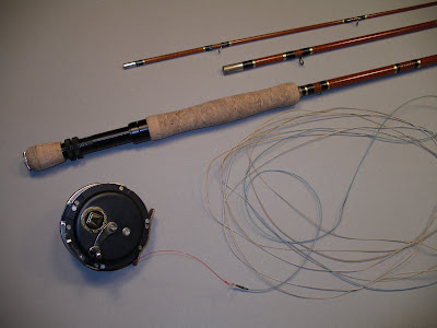
Fiberglass seemed like a good choice for carp. It’s strong, durable, can make a delicate presentation (carp are spooky), and can really “put the wood” to a fish. I started out hoping for a seven weight and finished with the nine weight you see here.
The blank for this rod came from Rick’s Rods. It is one of the few remaining Wright-McGill fiberglass blanks, and was full length. An uncut blank is not labeled. You select by feel. When the rod is complete you get out the lines and see what weight works best. The rod I will be describing in this blog is much lighter and feels “five-ish”, we’ll see.
In the next post I will discuss fishing this rod with the old Martin reel and a lead core shooting head line. Then we will get started on the new rod.
|
|


 This rod is about the experience, the tradition, and the uniqueness. There is not another one in the world. Someone may have a blank stored away, but Rick’s Rods doesn’t. I do have four other light weight blanks, but they are all sanded and would produce a different appearance.


